Blog post · September 9, 2026 · 10 min read
Coursing, Corner Conditions, and Panel Joints: The Three Details That Make or Break a Thin Brick Tilt-Up Facade
Thin brick tilt-up facades fail at three predictable details: coursing alignment, corner conditions, and panel joint integration. Here's how to design around all three before the pour.
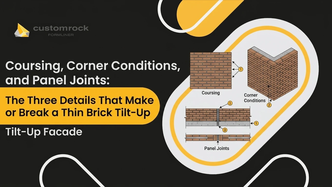
The thin brick facade looks convincing in the rendering. Then the panels go up, and the coursing doesn't land at the same height on either side of a panel joint. The corner has a half-brick floating at the edge with no return. The panel-to-panel reveal cuts straight through a soldier course. None of this was in the catalog photo.
These aren't pour defects. They're design development failures. And they're predictable, which means they're preventable, if you understand the constraint that governs all three of them.
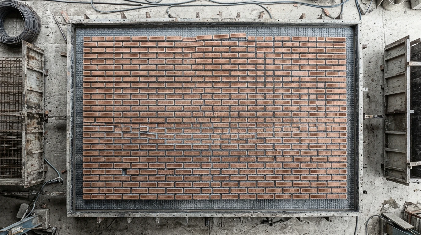
Here's the constraint: the brick layout is fixed the moment the liner is set on the casting bed. The thin brick pieces, roughly half an inch thick and sliced from full brick stock, go face-down into holders or liner templates before a single yard of concrete is placed. Once the pour happens, nothing moves. There's no field adjustment, no shimming, no cutting a course to fit. The coursing you get is the coursing you designed, or failed to design, at DD.
That's the logic that makes thin brick tilt-up panels different from a traditional laid-brick veneer. A mason can work around a bad dimension. A casting bed can't.
The First Problem: Coursing Alignment Across Panel Joints
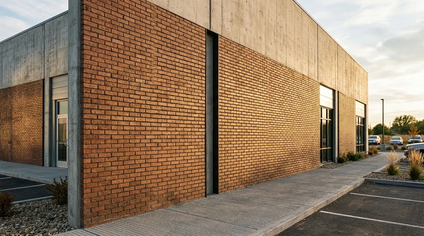
A tilt-up building is a collection of discrete panels, each poured flat and tilted into position. The structural logic of panel layout, including bay spacing, load paths, and openings, has nothing inherently to do with brick coursing modules. When those two systems aren't coordinated from the start, the coursing on Panel A arrives at the panel joint at a different height than the coursing on Panel B. The eye catches it immediately.
The fix is to treat panel dimensions the way you'd treat curtain wall bay spacing: build the geometry around the module, not the other way around. Standard modular brick runs at 2-5/8 inches high with a 3/8-inch joint, giving a 3-inch course height. A running bond pattern on a tilt-up panel needs to start and end at a full-course increment if you want the coursing to read continuously across a joint. That means panel heights and the vertical position of reveals need to be calculated against the brick module before the structural drawings are issued, not reconciled afterward.
Horizontal alignment is the same problem in the other direction. Running bond requires that the offset between panels maintains the half-brick stagger. If the panel joint falls at a point that breaks the stagger logic, you get two panels that each look fine individually but read as mismatched when you step back.
The practical move at DD: work with the liner manufacturer to produce a coursing diagram that overlays the brick module grid on the panel layout. This is a shop drawing problem disguised as a design problem. Manufacturers who supply thin brick formliner systems for precast and tilt-up typically have CAD and Revit details that include coursing layouts. Use them as a starting point, not an afterthought. If you delegate this coordination to the contractor, you're effectively delegating the appearance of the building.
The Second Problem: Corner Conditions
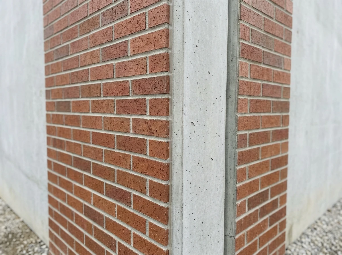
Corners are where the masonry illusion is most likely to break down. A real brick wall turns a corner through bonded masonry, with alternating headers and stretchers that physically interlock. A thin brick tilt-up panel can't do that. The panel is a flat slab. The corner is a concrete edge. The question is what you do with it.
There are three honest options, and one dishonest one.
Wrapped corner: The thin brick returns onto the adjacent face of the panel, simulating a bonded corner. This is achievable with purpose-made corner pieces, L-shaped thin brick units that cover both faces. It reads well at a distance and holds up to close inspection if the corner units are specified correctly and the coursing is coordinated on both faces simultaneously. Standard detail libraries from thin brick manufacturers include inside and outside corner treatments for exactly this condition. The coordination requirement is higher: both panel faces need to be laid out as a single coursing diagram, not two independent ones that happen to meet.
Returned corner (expressed concrete edge): The brick field stops short of the corner, and the concrete edge is expressed as a deliberate reveal or chamfer. This is the most defensible detail aesthetically, and it's honest about what the material is. A clean concrete return, especially with a slight chamfer or a contrasting liner texture, reads as a design decision rather than a limitation. For a commercial tilt-up building facade where the architecture already plays with material contrast, this approach can be the stronger choice.
Panel joint at corner: Some panel configurations place the vertical joint at or near the corner, which sidesteps the corner detail entirely. The joint becomes the corner. This only works if the structural layout accommodates it and the joint treatment is designed carefully, with a recessed reveal rather than a butt joint.
The dishonest option is attempting a wrapped corner without proper corner units and using cut field brick instead. The result is a corner with inconsistent joint widths, mismatched face textures, and coursing that doesn't align on both faces. It looks like what it is: a field improvisation. The grinding and patching required to clean it up typically cost more than specifying the correct corner units from the start.
The decision between these approaches needs to be made at DD, documented in the finish schedule, and carried through to the liner layout drawings. Corner conditions left to the contractor to resolve will be resolved for cost, not for design intent.
The Third Problem: Panel Joint Integration
The panel joint is a structural necessity. It's also a line that runs the full height of the building, and it will either read as part of the design or as a scar across the facade.
The default treatment, a sealant joint flush with the brick face, is the worst option visually. It cuts through coursing lines with no logic, and the sealant color rarely matches the mortar joint color closely enough to disappear. The joint reads as a discontinuity because it is one.
Two approaches work better.
Design the joint as a compositional line. A recessed reveal at the panel joint, wider than a mortar joint and clearly different in character, signals to the eye that this is an intentional break. The coursing on either side of the reveal doesn't need to align perfectly because the reveal itself absorbs the transition. This is the same logic that makes control joints in masonry walls readable: the break is acknowledged, not hidden. The reveal width, depth, and profile need to be specified in the drawings, not left to the contractor's standard practice.
Align the joint with a vertical coursing line. In running bond, every other course has a vertical joint at the same horizontal position. If the panel joint is positioned to coincide with one of those recurring vertical joints, the structural joint reads as a continuation of the bond pattern rather than an interruption. This requires the panel layout to be coordinated with the brick module in both dimensions simultaneously, which circles back to the coursing diagram from Problem One.
Some of the most resolved tilt-up facades combine multiple inlay textures across panel joints, using the joint as the transition between a brick field and a fluted rib band or a stone texture. The panel joint stops being a problem because it's been promoted to a compositional device. This is a legitimate design strategy, and it's worth considering early in schematic design rather than as a rescue move at the end of DD.
For more on how formliner pattern choices affect surface composition, the logic of combining textures across a facade applies whether you're working with brick, stone, or abstract relief.
Liner Selection and the Cost of Getting It Wrong
All three of these conditions get worse with lower liner quality. A plastic foam liner for thin brick tilt-up is adequate for a single pour on a budget project where the coursing is simple and the corner conditions are expressed rather than wrapped. For a project where the coursing needs to read continuously across multiple panels and the corners are wrapped, a urethane liner is the better choice, not because it's more expensive, but because the dimensional consistency is tighter and the brick holder geometry holds position more reliably through the pour.
The math is straightforward. Field corrections for misaligned coursing, including grinding, cutting, patching, and recoloring, add up quickly. The cost difference between a plastic liner and a urethane liner on a mid-size commercial facade is almost always less than the cost of one day of remedial work. Specifying the higher-quality liner is a cost-containment decision, not a luxury.
The manufacturing process behind a form liner order is worth understanding before you finalize the spec: dimensional tolerances are set during production, not adjusted on site, which means liner quality decisions made at procurement directly control what the finished wall looks like.
The Tilt-Up Construction Association publishes structural and best-practice resources for panel design that provide useful context for coordinating the structural and aesthetic requirements of panel joints simultaneously.
What to Specify at DD
By the end of design development, the finish schedule and the liner layout drawings should answer four questions:
What is the brick module, and how does panel height relate to it? Every panel height should be a whole-number multiple of the course height, or the deviation should be intentional and documented.
How are corners resolved? Wrapped with corner units, returned to expressed concrete, or jointed? The answer should be in the finish schedule with a reference detail.
How are panel joints treated? Reveal profile, width, depth, and sealant specification should all be called out. If the joint is designed to align with the coursing, that alignment should be shown in the coursing diagram.
Who is coordinating the liner layout with the form bed? This should be a named responsibility, not an assumption. The contractor needs a coursing diagram from the design team, not a catalog photo.
These aren't complicated details. But they're details that fall through the gap between design and construction if nobody owns them explicitly. The facade you get is the one that was designed at this stage, or the one the contractor improvised when the design wasn't specific enough.
FAQ
Why does coursing alignment fail so often on thin brick tilt-up projects?
Because panel dimensions are typically set by structural logic first, and brick modules are added later without checking whether the two systems are compatible. Standard modular brick runs on a 3-inch course height. If panel heights and reveal positions aren't calculated against that module at DD, the coursing on adjacent panels will land at different heights, and no field adjustment can fix it after the pour.
What is the most reliable corner detail for thin brick tilt-up?
It depends on the design intent. A wrapped corner using purpose-made L-shaped corner units reads as continuous masonry and holds up to close inspection, but it requires careful coordination of both panel faces as a single coursing diagram. An expressed concrete return is simpler to execute and more honest about the material. Attempting a wrapped corner with cut field brick instead of proper corner units is the detail most likely to fail.
Can panel joints be made to disappear on a thin brick tilt-up facade?
Rarely, and usually not worth trying. A flush sealant joint through a brick field almost never reads as a mortar joint. The more reliable approach is to design the joint as a deliberate compositional line: a recessed reveal that acknowledges the break, or a joint position that aligns with a recurring vertical in the bond pattern. Both strategies make the joint intentional rather than accidental.
When should liner selection be finalized relative to the rest of the design?
Before the structural drawings are issued. The liner layout needs to be coordinated with panel dimensions, and that coordination can affect panel sizing. Waiting until after the structural package is complete puts the liner layout in a reactive position, which is where field problems start. Liner selection and coursing coordination should be part of the DD deliverable, not a submittal review item.
What's the difference between plastic and urethane liners for thin brick tilt-up?
Plastic foam liners are lower cost and adequate for simple coursing on budget projects. Urethane liners have tighter dimensional tolerances and hold brick holder geometry more consistently through the pour, which matters when coursing needs to read continuously across multiple panels. For projects with wrapped corners or complex coursing, the cost difference between liner types is almost always less than the cost of remedial field work.
Who should own the coursing coordination between design and the casting bed?
The design team should produce the coursing diagram and own the design intent. The contractor and liner supplier execute against it. When this responsibility is left ambiguous, the contractor resolves it for cost and schedule, not for design intent. Naming a responsible party in the finish schedule or the spec section is a simple step that prevents most of the field improvisation that produces disappointing facades.